
Nand To Tetris #2: Constructing Logic Gates
There's a trick to constructing circuits, and the trick to discovering the trick is to not give up.

Chapter 1 of “Building a Modern Computer from First Principles” gives the student the project of constructing the basic logic gates from a single primitive gate, NAND.
I already had a familiarity with this subject from my degree program. If you don’t know what anything in that sentence means, here’s a Youtube crash course.
Most computers work by performing logical operations (which represent meaningful actions) on structures of binary data, or bits (which represent meaningful information).
You can think of logical operations a bit like following a recipe. You have some amount of meaningful input data (raw ingredients), and then you can combine logical gates to create “chips” (logic gates are just a simple type of chip) that predictably alter your data using logic, like steps in the recipe. With enough steps (and fancy math tricks), you can take a small number of variables and compute incredibly sophisticated information. This is how graphing calculators work. Provide the slope and it can plot a graph for you, just by performing predictable, logical steps on your input data.
The first step to building such a system is to figure out the base set of logical operations that you will find useful when designing an arithmetic chip, a storage chip, and a communication system between chips. Here are 15 chips that we will want access to:
reminder: a chip is just any technology that turns binary inputs into binary outputs. These are all “logic chips”, so they transform the binary inputs according to the logical operation they are named after. If this is still confusing, watch the crash course above.

The core insight that allows us to get started designing chips is that all logic chips can be constructed from NAND chips.
The amazing, cool, exciting, remarkable, brilliant thing, though, is that as soon as I design a chip, I can use it in all my future designs! I can invent new logical technologies that I can then combine to invent even more new technologies, and so on…
This is an addicting feedback loop, and it’s impossible to describe what it feels like in words to use something you just invented to invent a new thing. You just have to try it yourself. Go ahead and invent these 15 gates for yourself, I dare you. If you want a buddy to consult, shoot me a message.
My notes from designing the basic logic chips:
This is a very empowering exercise. In the beginning, I was struggling to remember my logic class. By the end, I had all these cool mental tricks that I was developing to think about how the logic flows and to translate these logical operations into the language of my own body (which often meant translating them to visual or programming metaphors in English that I understood well)
I highly recommend this first chapter to others. Use YouTube vigorously.
I gained an intuitive understanding of Multiplexers and Demultiplexers that I didn’t have when I learned about logic gates in college. Here’s the video that really helped me:
The core insight is that Multiplexers and Demultiplexers are both just “switch statements” (e.g. long lists of if-then statements).
Part of the confusion is the names. These names come from the sound + communication engineering world, where you would literally "multiplex" multiple inputs into a single controller, which would then give you a switch to select the signal that you want, and maybe even another switch to "route" (Demultiplex) that signal to one of many outputs channels.
If I were to rename them, I’d say:
Multiplexor = selector (select one input from many)
Demultiplexer = router (route to one output of many)
This also led to a general understanding of how I can program "if else" and "switch" statements in hardware.
Switch statements need 2 things, though often they have 3.
a. A Condition for switching
b. An output for each condition
c. (Optional but common in practice) an input to calculate the output from
Boolean conditional statements are now somewhat obvious to me:
"if(x) A else B" statements in hardware can be modeled by:
Given a condition X and two conditional outputs A and B
1. invert X, so you also have !X
2. get X + A
3. get !X + B
4. OR these two together, so you have if X, then A OR else B
These conditional statements can be extended to n-way cases if you don’t want to create a combinational circuit1 of nested MUX gates.
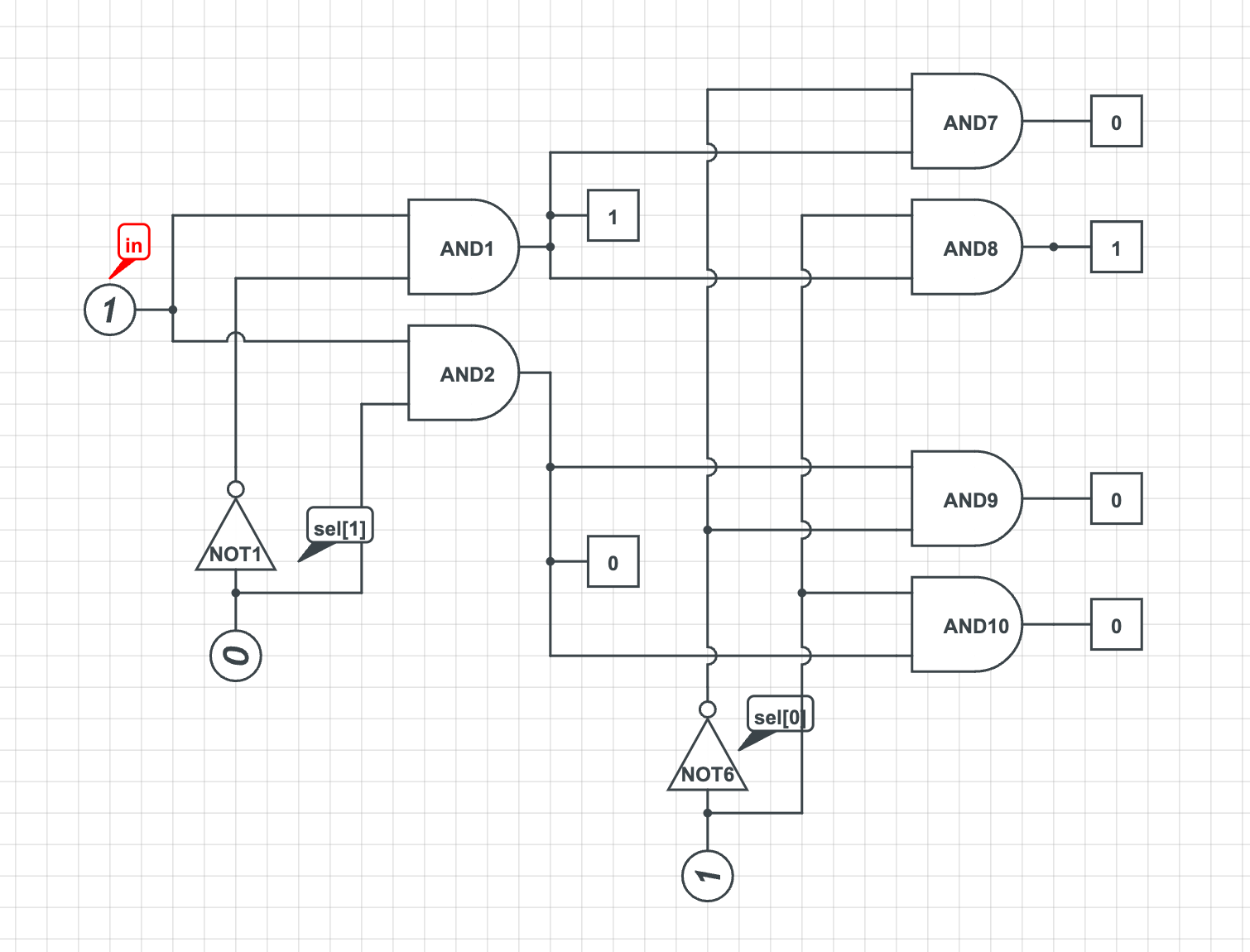
The general formula for an n-way multiplexer is as follows:
1. For each bit in the n-bit select code (say 3-bits, 000, 001 ... 111), get its inversion, too.
2. For each bit in your input (say 8-bits, 00000000... 11111111), in[0]...in[7], assign it to a code of your multiplexer.
2b. So in[0] -> 000, in[1] -> 001, ... in[7] -> 111
3. Now that each input bit has an assigned 3-bit code, you can use a 4-way AND gate
3a. for in[0] -> 000, make AND(in[0], !sel[0], !sel[1], !sel[2]), which translates to IF (!sel[0] + !sel[1] + !sel[2]) THEN output in[0]
3b. do this for every input bit in[0]... in[7], giving each a unique pattern of sel bits
5. now you have 8 output lines, each of which says: if[sel=000]: in[0]; if[sel=001]: in[1];... if[sel=111]: in[7]; Only one can ever be true at a time since they’re mutually exclusive, and each corresponds to one of the 8 inputs.
6. tie all 8 lines together into an OR statement, so you get whichever input was selected
7. DONE. You have a multiplexer/switch circuit.
A combination circuit just means combining many lower-level circuits of the same type into a higher level one. I can construct a 16-way MUX directly via AND and not gates (or even just from NAND), or I can construct it using 3 MUX4Ways, which I could each construct using 3 basic MUX. If this doesn’t mean anything to you, I’d recommend going to youtube or starting the course :) message me if you want help